BMW E46 angel eyes installation

This is a backup from BMWclubmalaysia forum

Hello all, I would like to share my angel eyes installation done a few weeks ago. Before I start here are some info regarding the car and the angel eyes.

Car: E46 facelift with halogens
Angel eyes: Umnitza Orion Lite Generic LED 6000K $59.99

Note: Try this at your own risk, I would not be responsible for any loss caused by following these installation steps. Please take all necessary precautions when doing your installation.

I started with the power wiring harness. The positive is taken from the jump start point.

The wiring harness comes with two triggers, one for normal and another for remote operation – lighting the car up along with the cabin lighting. The remote lighting is not used for now so it is insulated away.

The negative is taken from a nearby chasis screw, which is also used to mount the relay.Then its time to remove the headlights lens to install the angel eyes. To do this there are a few things need to be done, remove the turn signal by releasing a screw from the top, remove plastic piece underneath headlight from middle of car towards the side, remove weather stripping on top of headlight, remove lens by releasing clips around it and pull out plastic piece.

The rings

Then the wires need to be fished through the headlight out to the back

Install clips on the ring

Fit the ring on the reflector

Test the ring before assembling the lens by energizing the relay with the jump start point with the normal operation trigger.

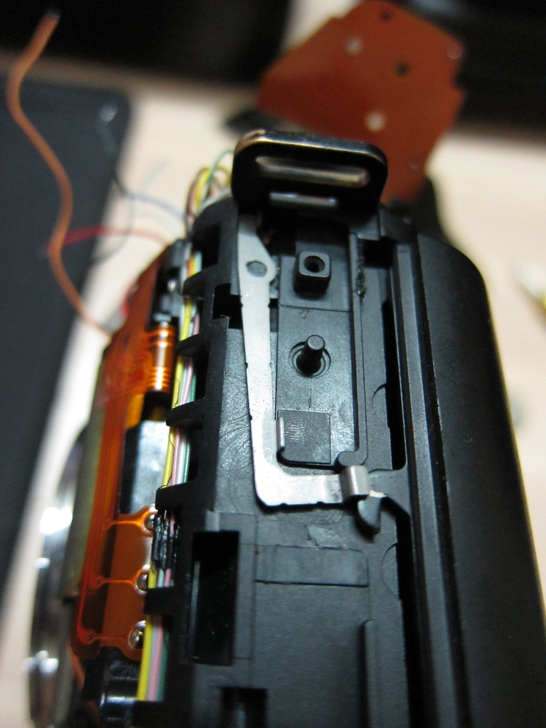
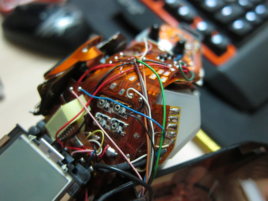
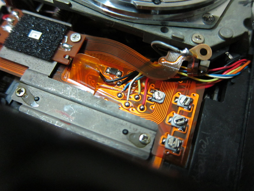
After the rings are installed, it’s time to find a point to energize the relay when the car is operating. I’m going for the always on mode where the lights is on whenever the key is in position 2. Remove the cover for wiring box using allen/hex keys. Other guides mentioned T25 for the screw but mine is secured using just allen keys. Umnitza guide mentioned splicing a red wire with gold/yellow stripe but I couldn’t find it. So I splice the following wire instead.

Before finishing up

All done

Cheers

[EDIT]

Remote trigger wiringThe wiring harness has another trigger which was not connected last time. It is meant to be connected to the footwell light so the angel eyes will light up along with the cabin. Since the cabin light fades out, so will the angel eyes.The unused trigger last time

Found a rubber seal at the firewall, punch through it and fish the trigger wire into cabin

Closeup

Displace plastic cover below steering to access wiringTrigger through firewall

Footwell light socket

Positive wire spliced

Connect trigger wire

Now you have remotely operated angel eyes. Cheers

Aidil

Canon T90 disassembly – fixing the shutter

This post is to share the steps and pictures for wires connection and parts location involved during the disassembly. I couldn’t fix mine due to the weak magnet, as the contacts are all clean. These steps are taken directly from Canon T90 service manual. You can find out how to remove the main cover from somewhere else, as this post will detail steps after that.

After the front and side cover is removed, I went ahead to remove the door latch components as a lot of guides online indicated that the spring might fly off.

Then the top cover is removed and all wires disconnected

Start text extraction from service manual

Sequence to remove mirror box, shutter block:
1. disconnect gray wire from solder lug, front release side of mirror box, Fig. 4 (or remove screw holding solder lug)

2. unsolder wires, front release side of main flex, Fig. 4
Note: Fig. 29 shows the wire positions to the front of the main flex (upper right-hand corner of drawing).

3. unsolder red and gray wires from self LED, Fig. 4.

4.- remove pressure bar, front flex connector (2 screws), Fig. 4
5. separate top flex section (SP flex) from flex-connector pins
6. remove elastic connector that fits over flex-connector pins
7. desolder main flex from V-BAT pin, front, Fig. 29
8. separate main flex from flex-connector pins
9. remove elastic connector that fits over flex-connector pins
10. unsolder wires, top rewind end, Fig. 28

11. remove switch rubber, top rewind end (large shoulder screw)
12. remove flex screw, top rewind end
13. desolder 2 connections of back-cover switch from main flex, top rewind end
14. separate top rewind end of main flex from camera
15. lift out mode-switch (plastic support) plate, top rewind end
16. desolder DX flex from FD flex, top rewind end (9 connections)
17. desolder FD flex from back-cover switch contact, top rewind end
18. remove eyelens, 2 long screws top

19. remove 3 screws holding external LCD (white screw goes at release end, toward back of camera)

20. unsolder black and red LCD-illuminator wires, top of main flex

21. unfold section of flex with external LCD
22. unsolder black, yellow, and blue sprocket-switch wires from main flex

23. desolder 5 connections of shutter flex from main flex
Note: in early versions of the flex, only the top 3 connections solder directly to the shutter flex. Wires connect the 1st-curtain and 2nd-curtain switch contacts on the shutter flex to the switch-test points on the main flex, Fig. Z8 (brown wire for 1st-curtain switch, white wire for 2nd-curtain switch). On
disassembly, unsolder the wires from the shutter flex

24. disconnect and remove stop-down spring, bottom of minor box
25. remove 2 black mirror-box screws, back by eyelens

26. remove 2 locating screws, front bottom of mirror box
27. lift out mirror box together with main flex
28. remove 2 screws holding plastic support plate, Fig. 10
29. unsolder orange wire from front of shutter block, Fig. 10
30. remove 3 screws holding shutter block (top 2 corners, bottom left-hand corner)
31. lift out shutter block
Note: To charge the mirror boig push forward the charge lever, Fig. 11. Release the mirror by pushing the armature of the release magnet, Fig. 11, away from the core (or push the tab, Fig. 11, toward the front of the mirror box). To return the mirror, disengage the mirror-up latch, Fig. 13. For mechanical operation and troubleshooting of the shutter block, see TROUBLESHOOTING (Testing the shutter block).

End of text extraction from service manual

To energize the shutter solenoid, you can supply 3v to the orange (positive) and black (negative) wire. To access that I desolder more wires, pictures below

Pictures of the mirror box out


pictures reuploaded to imagevenue