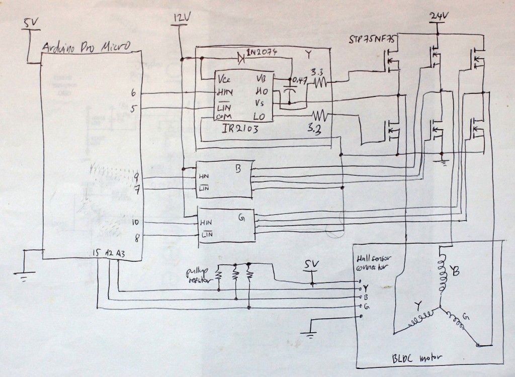
UPDATE : May 12, 2015, I’ve added schematic after the Arduino sketch below
I couldn’t find much info on this on the net so I thought to share my experiment for those researching on this.
Hardware as follows
Arduino – Pro Micro 5V
Mosfet – STP75NF75
Half bridge driver – IR2103
Three PWM outputs are used in this design to pulse the upper mosfets while the bottom mosfets are either on or off.
//Knobs

const int analogInPin1 = A0;  // Analog input pin that the potentiometer is attached to
int sensorValue1 = 0; // value read from the pot
int outputValue1 = 0; // value output to the P
//hall input
int hall_sensor_y = A3;
int hall_sensor_b = A2;
int hall_sensor_g = 15;
//buzzer and LED
int buzzer = 16;
int LED = 17;
float throttle = 0.0;
boolean MotorOff = false;
float Cn = 0;
//Motor setup
const int y_motor_lout = 5;
const int y_motor_pwm_hout = 6;
const int b_motor_lout = 7;
const int b_motor_pwm_hout = 9;
const int g_motor_lout = 8;
const int g_motor_pwm_hout = 10;
enum WheelDirection {
DIR_FORWARD,
DIR_BACKWARD,
DIR_STOP
};
// MOTOR DRIVE
void MoveWheel(WheelDirection (dir), float (speed)) {
if (MotorOff) return;
//empty all motor registers
//half bridge driver, hi part is active high
//lo part is active low
analogWrite(y_motor_pwm_hout, 0);//set motor to stop
analogWrite(b_motor_pwm_hout, 0);
analogWrite(g_motor_pwm_hout, 0);
digitalWrite(y_motor_lout, HIGH);
digitalWrite(b_motor_lout, HIGH);
digitalWrite(g_motor_lout, HIGH);
int hall_y = digitalRead(hall_sensor_y);
int hall_b = digitalRead(hall_sensor_b);
int hall_g = digitalRead(hall_sensor_g);
//Serial.print("\r\n");
//Serial.print(hall_y);
//Serial.print(hall_b);
//Serial.print(hall_g);
if (dir == DIR_STOP) {
// do nothing
} else if (dir == DIR_FORWARD) {
if (hall_y == 0 && hall_b == 0 && hall_g == 1) {//001
analogWrite(b_motor_pwm_hout, speed);
digitalWrite(g_motor_lout, LOW);
} else if (hall_y == 1 && hall_b == 0 && hall_g == 1) {//101
analogWrite(b_motor_pwm_hout, speed);
digitalWrite(y_motor_lout, LOW);
} else if (hall_y == 1 && hall_b == 0 && hall_g == 0) {//100
analogWrite(g_motor_pwm_hout, speed);
digitalWrite(y_motor_lout, LOW);
} else if (hall_y == 1 && hall_b == 1 && hall_g == 0) {//110
analogWrite(g_motor_pwm_hout, speed);
digitalWrite(b_motor_lout, LOW);
} else if (hall_y == 0 && hall_b == 1 && hall_g == 0) {//010
analogWrite(y_motor_pwm_hout, speed);
digitalWrite(b_motor_lout, LOW);
} else if (hall_y == 0 && hall_b == 1 && hall_g == 1) {//011
analogWrite(y_motor_pwm_hout, speed);
digitalWrite(g_motor_lout, LOW);
}
} else if (dir == DIR_BACKWARD) {
if (hall_y == 0 && hall_b == 0 && hall_g == 1) {//001
analogWrite(g_motor_pwm_hout, speed);
digitalWrite(b_motor_lout, LOW);
} else if (hall_y == 1 && hall_b == 0 && hall_g == 1) {//101
analogWrite(y_motor_pwm_hout, speed);
digitalWrite(b_motor_lout, LOW);
} else if (hall_y == 1 && hall_b == 0 && hall_g == 0) {//100
analogWrite(y_motor_pwm_hout, speed);
digitalWrite(g_motor_lout, LOW);
} else if (hall_y == 1 && hall_b == 1 && hall_g == 0) {//110
analogWrite(b_motor_pwm_hout, speed);
digitalWrite(g_motor_lout, LOW);
} else if (hall_y == 0 && hall_b == 1 && hall_g == 0) {//010
analogWrite(b_motor_pwm_hout, speed);
digitalWrite(y_motor_lout, LOW);
} else if (hall_y == 0 && hall_b == 1 && hall_g == 1) {//011
analogWrite(g_motor_pwm_hout, speed);
digitalWrite(y_motor_lout, LOW);
}
}
delay(10);
}
void setup()
{
//Serial.begin(115200);
pinMode(y_motor_lout, OUTPUT);
pinMode(y_motor_pwm_hout, OUTPUT);
pinMode(b_motor_lout, OUTPUT);
pinMode(b_motor_pwm_hout, OUTPUT);
pinMode(g_motor_lout, OUTPUT);
pinMode(g_motor_pwm_hout, OUTPUT);
pinMode(buzzer, OUTPUT);
pinMode(LED, OUTPUT);
pinMode(hall_sensor_y, INPUT);
pinMode(hall_sensor_b, INPUT);
pinMode(hall_sensor_g, INPUT);
//half bridge driver, hi part is active high
// lo part is active low
analogWrite(y_motor_pwm_hout, 0);//set motor to stop
analogWrite(b_motor_pwm_hout, 0);
analogWrite(g_motor_pwm_hout, 0);
digitalWrite(y_motor_lout, HIGH);
digitalWrite(b_motor_lout, HIGH);
digitalWrite(g_motor_lout, HIGH);
}
void loop()
{
// read the tuning knob value:
for(int i=0;i<5;i++){
sensorValue1 += analogRead (analogInPin1);
}
sensorValue1 = sensorValue1/5;
// map tuning knob to the range of the analog out:
outputValue1 = map(sensorValue1, 0, 1023, -90, 90);
//PID CALC
Cn = outputValue1;
//MOTOR DRIVE
WheelDirection dir;
if (Cn > 0)
dir = DIR_FORWARD;
else if (Cn < -0)
dir = DIR_BACKWARD;
else
dir = DIR_STOP;
throttle = abs(Cn);
MoveWheel(dir, throttle);
}
May 12, 2015 - Hi, due to quite a few requests on the circuit I've decided to draw it out and post it here. The components for the half-bridge driver is picked up from http://www.irf.com/technical-info/appnotes/an-978.pdf . The schematic below shows that the motor is driven by 24V power source, you can use higher voltage as long as it meets the rating of the MOSFET. Guys, please use the schematic at your own risk and please take necessary precaution when working with high voltage. I suggest test your circuit and motor at low voltage first before supplying full voltage. Again, I should stress that this is how I do it in respect to my hardware (Arduino) limitation, your project should use this as a base and expand to fix it's flaws. Cheers
